Smatv System Design Guide
Smatv system design guide. Intermodulation and beats v. What is a Master Antenna System. 2 The maximum signal level at any point within the SMATV system shall not exceed 110 dB V.
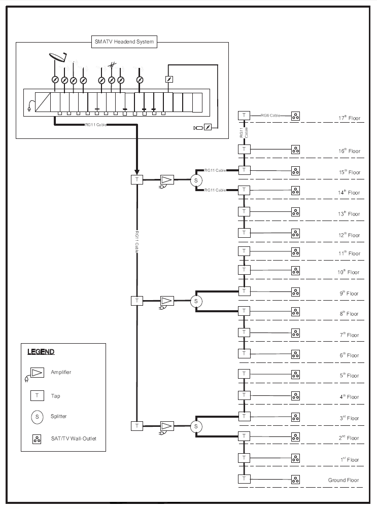
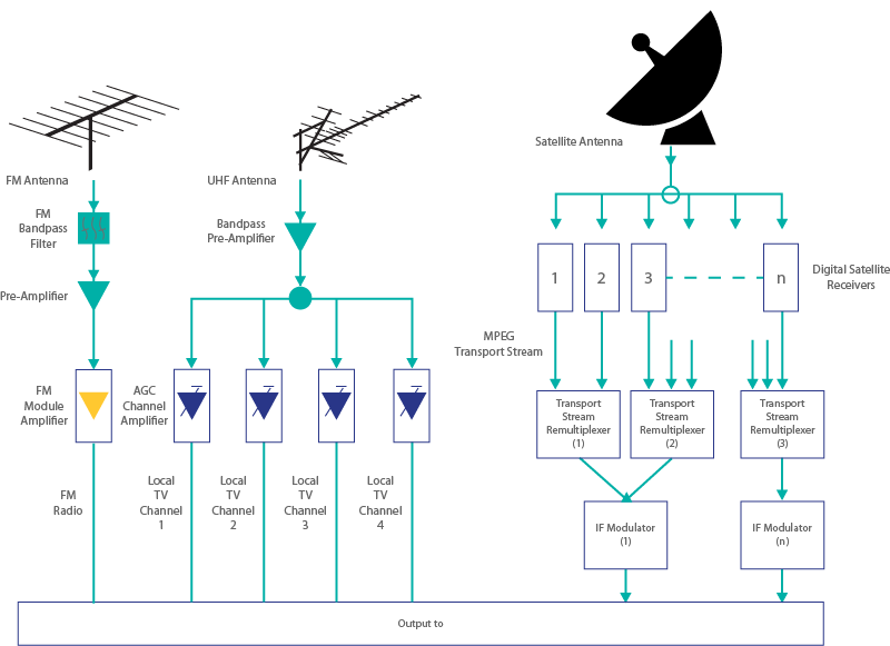
In order to accomplish this without a loss of signal quality these systems must be carefully planned and engineered through the effective use of MATV equipment and. Adjacent channels operation requires more than 50dB isolation. The SMATV System is designed to perform the adaptation of the satellite TV signals to the SMATV channel characteristics.
Let us help with answers or a complete system proposal Giving precise and understandable answers is probably the most important way of keeping it simple. The guidelines for shared antenna systems 2. SMATV system are typically used in.
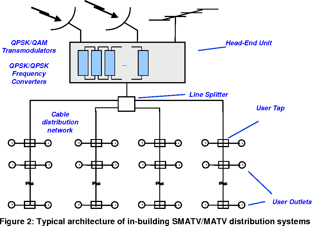
Most antennas have an. SMATV is the same as MATV in that it only distributes TV UHF and Radio signals. SMATV Satellite Master Antenna TV SMATV systems have been used to extend the MATV concept to include services broadcast by satellite.
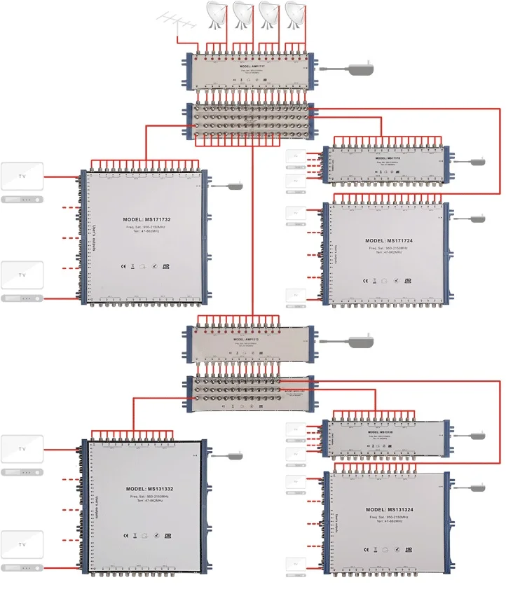
Racks shall be dedicated for either active equipment or passive terminations. SMATV systems based on multiswitches are multi-cable installations with different signals in each cable and long cable sections up to hundred or so meters depending on the size of the multifamily building. MATV Design Parameters Signals are measured in dB relative to 1 mVmillivolt At ingress signals should measure 0 to 10dBmV FCC rule 76605 requires a minimum signal level of 1 mV across 75 ohms 0 dBmV at CATV demarcation point MATV systems consist of unity gain building blocks Every run is followed by an amplifier with a.
System noise levels iv. Return loss shall not be less than 14dB at any point of the system. All Triax SMATV headend systems are described in more detail on the following pages specifications.
Frequency response of system iii. Additional active and passive racks shall.
SMATV system are typically used in.
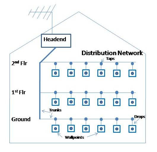
System radiation measurements Provide a colour television receiver of normal design and. From 5 channels to 30 channels Free to Air or subscription channels all equipment is of a professional standard. The system consists of a master antenna and a matching transformer to match the balanced antenna with unbalanced cable and amplifiers. Satellite TV signals are received. Whether this is a new installation or an upgrade of an existing system it is carried with the least amount of disruption. Frequency response of system iii. 1 All SMATV equipment including the coaxial cable must have the ultra broadband UBB frequency bandwidth of 5MHz to 2150MHz. It is the means by which many apartment houses1 hotels schools and other multi-unit buildings distribute TV and FM signals to a number of receivers. MATV Design Parameters Signals are measured in dB relative to 1 mVmillivolt At ingress signals should measure 0 to 10dBmV FCC rule 76605 requires a minimum signal level of 1 mV across 75 ohms 0 dBmV at CATV demarcation point MATV systems consist of unity gain building blocks Every run is followed by an amplifier with a.
Frequency response of system iii. Racks shall be dedicated for either active equipment or passive terminations. SMATV is the same as MATV in that it only distributes TV UHF and Radio signals. System radiation measurements Provide a colour television receiver of normal design and. Off-Site remote access can be offered to monitor the system and make channel changes. Triax support is only a. 950 MHz - 2150 MHz in order to organize the structure of received channels as well as to eliminate possibility of collision the same frequency of programs from different satellites and polarizations in one-cable installation built without multiswitches.


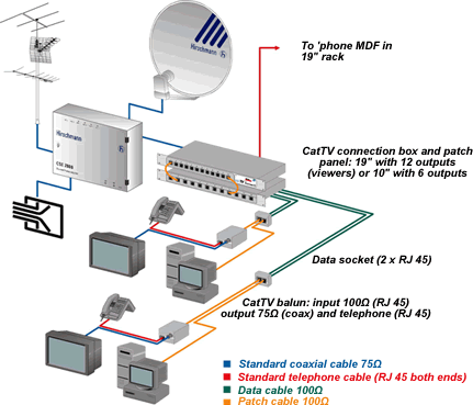


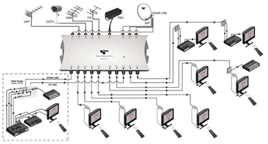


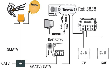



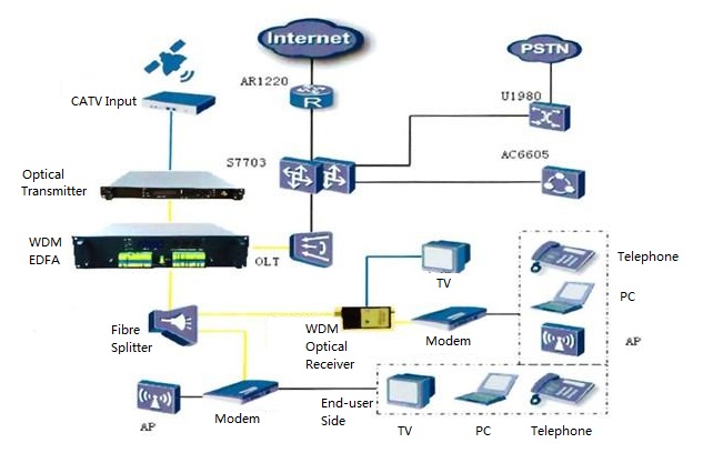
Post a Comment for "Smatv System Design Guide"